#Serial Port Device Driver Development
Explore tagged Tumblr posts
Visit Tumblr Blog
Explore Tumblr blogs with no restrictions, modern design and the best experience.
Last Seen Tumblr Blogs


Fun Fact
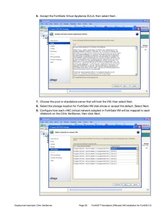
Hackers stole 65M passwords from Tumblr in 2013.
Text
Device Driver Development
Linux Device Driver Development - Project-Based Training Program, Our Linux Project-Based Training in Device Driver Development is a comprehensive, hands-on program tailored for engineering graduates and postgraduates. Whether you are pursuing BE, B.Tech, ME, M.Tech in Electronics, Computer Science, Information Technology, or Instrumentation, or have a Master's in Computer Applications (MCA), this course equips you with industrial-level skills and real-time project experience.
Why Choose This Program?
This training is designed to bridge the gap between academic knowledge and professional expertise. It transforms you from a student into an industry-ready professional, empowering you to work with innovative and in-demand technologies. You will gain in-depth knowledge of Linux-based systems, system administration, network management, and software development processes.
Key Focus Areas
Linux Operating Systems: Hands-on training with Fedora, Ubuntu, and Debian distributions.
System & Network Administration: Learn to configure, manage, and troubleshoot Linux systems.
Programming Skills: Master C Programming, the foundation for developing Linux Device Drivers.
Embedded Linux & ARM: Gain practical exposure to embedded systems and ARM-based architectures.
Device Driver Development: Focus on character device drivers, an essential area for hardware-software interaction.
Real-Time Projects & Industrial Training
The program emphasizes project-based learning, where you will work on real-world projects to design, develop, and test Linux device drivers. You'll also explore software design and development, learning to solve practical industrial challenges. This ensures you gain hands-on expertise while understanding how industries approach complex systems.
Career Benefits
On completion, you will be well-prepared for roles in embedded systems, system programming, device driver development, and software engineering. This training opens pathways to careers in industries ranging from consumer electronics to automotive and IoT.
If you are eager to advance your technical skills, understand industrial workflows, and build a solid career foundation in Linux technologies, this program is your gateway to success!
Industrial Training Serial Port Device Driver , Industrial Training Device Driver Design , Industrial Training Device Drivers Development , Project based Training Device Drivers.
#Device Driver Development#Character Device Driver Development#Introduction to Device Driver Architecture#Parallel Port Device Driver Development#Serial Port Device Driver Development#Block Device Driver Development
0 notes
Text
Engineer II - Linux Automotive
Job title: Engineer II – Linux Automotive Company: Harman Job description: like kernel random crash. Good exposure on board bri ng-up, boot loaders, device driver porting. Good exposure on serial… professional and personal development. You Belong Here HARMAN is committed to making every employee feel welcomed, valued… Expected salary: Location: Bangalore, Karnataka Job date: Sun, 25 May 2025…
0 notes
Text
Solution for Thermal Printers Using the KT6368A Dual-Mode Bluetooth Chip Module
I. Introduction to the Printer Bluetooth Module
Currently, most mainstream printers do not come equipped with Bluetooth. Due to cost constraints and other factors, many still rely on USB for communication with computers to facilitate data exchange for printing.
In the early days, Bluetooth technology developed slowly, and printer-type products were positioned as high-end, making development quite challenging. For example, a requirement to connect one iOS device and seven Android host devices simultaneously to send print data was nearly impossible to achieve cost-effectively.
Most current module products consist of an MCU paired with a Realtek dual-mode Bluetooth chip. The reason for this combination remains unclear to us.
However, in reality, many products do not require such high specifications. Connecting to a single host device is often sufficient. For scenarios requiring simultaneous multi-device operation, Wi-Fi or 4G versions are typically used instead.
Additionally, modern Windows 10 computers come with built-in Bluetooth drivers, and Bluetooth adapters are readily available and convenient to use.
The early Bluetooth module designs were as follows:
We recommend using the KT6368A dual-mode Bluetooth chip, which enables APP connectivity and data exchange for printers. It comes in an SOP8 package, offering high cost-effectiveness, simplicity, and stability.
II. Detailed Development Guide
1. First, ensure that your Bluetooth printer supports BLE (Bluetooth Low Energy) communication and does not use proprietary protocols, adhering to standard BLE communication protocols.
2. Obtain UUIDs from the Printer Manufacturer
Request the printer's UUIDs from the manufacturer. There are three UUIDs:
Service UUID
TX_UUID (Transmit UUID)
RX_UUID (Receive UUID)
3. Configure the Bluetooth Module Using AT Commands
Enter AT command mode to modify the BLE UUIDs. Update all three UUIDs (Service, TX, and RX).
Set the BLE working mode to Master Mode.
Send the command AT+Z to restart the module.
The UUIDs for the KT6368A are as follows:
Service_UUID: 49535343-FE7D-4AE5-8FA9-9FAFD205E455
TX_UUID: 49535343-1E4D-4BD9-BA61-23C647249616
RX_UUID: 49535343-8841-43F4-A8D4-ECBE34729BB3
III. Test Environment Setup – Meituan Merchant Edition

The Android and iOS platforms operate differently:
Android uses SPP (Serial Port Profile) for communication.
iOS devices use BLE (Bluetooth Low Energy).
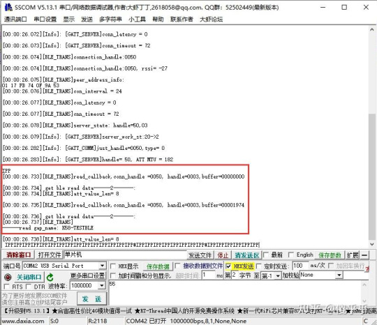
The KT6368A chip's internal operation logs and the print data received from the app can be monitored for debugging and verification.
#BluetoothPrinters #Bluetoothchip #AIoT #EmbeddedSystems #electronics #BLE #KT6368A
0 notes
Text
Open source 24-channel USB high-voltage driver
When it comes to automation and control systems, there's often a need for multiple digitally controlled output terminals with high-voltage handling capabilities. Many existing modules are bulky, expensive, or require numerous additional components to function. To address this gap, I've developed a fully open-source, USB-controlled 24-channel high-voltage driver. This device provides precise, flexible control in a compact and user-friendly package. The project is open hardware, released under the CERN-OHL-W license, ensuring transparency from hardware schematics to firmware code. The driver module communicates via USB using a simple virtual COM port, eliminating the need for special drivers and complex setups.

At the core of the system are three TPIC6B595 shift registers, each supplying eight open-drain outputs that can handle up to 50V and sink currents of up to 150mA per channel. These registers are daisy-chained to achieve a total of 24 outputs. The outputs are designed for low-side switching and include integrated clamping diodes, making them suitable for driving inductive loads such as relays and solenoids. Data is clocked into the registers through serial input from a microcontroller, allowing for fast and reliable state updates across all channels with just a few lines of code.
The logic and communication for this module are managed by the STC15W204S microcontroller, a cost-effective yet powerful 8051-based MCU with enhanced UART performance and an integrated oscillator. This chip is paired with a CH340N USB-to-UART bridge, which presents the device as a standard virtual COM port to the host PC. Upon connection, the microcontroller listens for a set of AT-style commands sent over the serial connection. These commands are straightforward and user-friendly, for example, "ON=65280" activates the middle 8 outputs, "CLR" turns off all channels, and "VER" retrieves the firmware version. Additionally, there is a command to save the current output state to the built-in EEPROM, enabling the system to restore its output to a known state after power cycles. This interface design is perfect for scripting, automation, or integration with software tools such as Python, LabVIEW, or custom control GUIs.
The PCB is designed using KiCad and features a 2-layer layout measuring 75.25mm × 33.75mm. It includes 2.54mm pitch headers for output connections and is equipped with a USB Type-C connector. Power can be supplied through either USB or an external regulated 5V source, which can be selected via onboard jumper settings. The layout ensures clean signal routing and minimizes crosstalk or interference, even when switching high-voltage loads. Careful decoupling and protection components provide robustness for real-world applications.

The PCB for this module was fabricated by PCBWay, who generously sponsored this project. PCBWay offers high-quality PCB manufacturing and assembling services. Also, they offer CNC and 3D printing services. The PCB of this module is available to order from PCBWay. Check out the PCBWay website for its manufacturing capabilities and pricing.
The firmware for the STC15W204S is written in C using SDCC. It is easy to expand the command set, introduce new communication modes, or add timed control logic as needed. The current implementation allows full 24-bit output control using a base 10 numerical mask, making it both scriptable and human-readable. Thanks to the preloaded bootloader of the STC15W204S, firmware updates can be performed through the same serial interface. Details about this process are covered in the project documentation. Like the hardware, the firmware is released under the MIT License and is available in the project repository.
The system has been tested with a variety of 12V and 24V inductive and resistive loads, including relay banks, solenoids, and LED arrays. Since the outputs are open-drain, external voltages up to 50V can be safely switched on each channel making it ideal for a range of industrial, laboratory, or artistic applications. Output timing is reliable, with clean edge transitions observed during scope testing, and no signal integrity issues even during full 24-channel toggling. It is recommended to use individual heatsinks for the driver ICs when driving high-current inductive loads with this module. While the printed circuit board has heat transfer traces, the addition of individual heatsinks can increase the durability of the module.

Potential use cases for this module include automated test benches, home automation systems, signal routing for instrumentation, nixie tube multiplexing, and other high-voltage control tasks. The command-based protocol makes it easy to script operations or integrate this module into a larger system.
For those who wish to explore the schematics, command protocol, design rationale, and usage examples in greater depth, I have published comprehensive documentation and resources in the project wiki. This includes detailed assembly instructions, firmware flashing guidance, and tips on customizing the firmware for enhanced functionality.
All source files - including schematics, PCB layout, firmware code, and the bill of materials - are freely available at https://github.com/dilshan/24ch-usb-high-voltage-driver.
0 notes
Text
【step by step】Easyi3C Host I3C adapter (2)
Easyi3C is a leading supplier of embedded system tools that simplify the development and debugging of various communication protocols. The company offers a range of products designed to help engineers and developers use I3C/I2C , USB and MIPI, JEDEC, MCTP and other protocols more efficiently.
Easyi3C Host I3C/I2C adapter is based on USB to I3C/I2C protocol, so you need to install USB driver first. Products on the market are generally based on USB to serial port, but the problem with this method is that the speed is slow and the serial port is not very stable. In order to solve this pain point, Easyi3C is directly based on USB protocol transmission, which improves the speed of data transmission and increases the stability of transmission, which is conducive to chip stress testing and long-term periodic cycle testing of chips, such as stress testing of PMIC chips.
The following is the installation process of the USB driver of Easyi3C. On the Windows platform, the installation is based on the GUI graphical interface, which is convenient and easy to use.
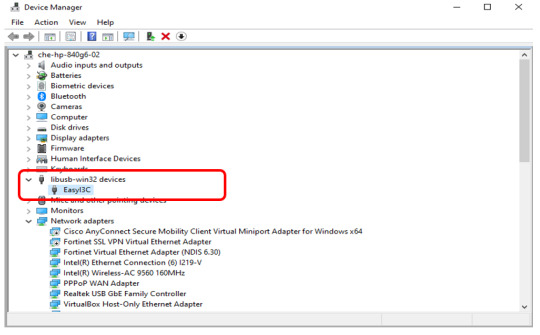
1. First, connect the Easyi3C Host I3C/I2C adapter to the computer via a USB Type-C cable. If the USB driver is not installed, the Windows device manager will display as follows:

2. You can now download the “Easyi3C Tower USB Driver Installer Tool.zip” file from the Easyi3C company’s official website.
3. Unzip the downloaded file above, and then open the program as shown below:

4. Select to install the USB driver as shown below:

5. If the USB driver is installed successfully, the following will be displayed in the Device Manager:
Through the above steps, the USB driver of Easyi3C has been installed successfully. Next, let’s continue to learn more about the product.
0 notes
Text
How do mobile devices wirelessly control LED screens?
With the rapid development of technology, mobile devices such as mobile phones and iPads have acquired many functions of traditional computers, including online office tasks. Nowadays, it is becoming more and more common to use these mobile devices to control LED displays. So, how do they control LED displays? This article will analyze this process and the principles behind it in detail.

Connection and control principle
Mobile phones and iPads can establish a connection with LED displays through wireless networks, without the need to use network cables like computers. This connection method mainly relies on wireless technologies such as WiFi, which enables mobile devices to easily control LED displays. Provide you with technical answers for wireless LED displays.
How to control LED displays with mobile phones and iPads
1.1 WIFI wireless control
WiFi wireless control is currently the most commonly used method. Mobile devices (such as mobile phones and iPads) are used as control terminals. Through touch screen operation, remote wireless control of LED displays can be achieved. All functions can be completed through touch screen, achieving zero-second switching without lag. This method completely abandons the traditional keyboard and mouse, and software replaces hardware.
Working principle: By adding a wireless router or other wireless device to the LED display, it can be bridged with the user's existing wireless network to form a wireless LAN. In this way, the network control card can be easily integrated into the wireless network to achieve wireless network control.

Features:
No wiring is required, easy installation and debugging Fast data transmission speed Required equipment: bridge, wireless router (it is recommended to choose a device with replaceable antenna to enhance the wireless signal reception effect)
Disadvantages: The communication distance of WiFi wireless control mainly depends on the gain capability of the bridge, and the communication distance of the wireless router is short, and the signal through the wall is weak or no signal. Therefore, this method is suitable for places with short-range wireless signals. If the area where the LED display is located is already covered by wireless signals, just bridge the wireless router connected to the LED display control card to the wireless network, and the display can be controlled on any device in the intranet.
1.2 RF wireless control
Working principle: One end of the RF module is connected to the control computer, and the other end is connected to the serial port of the control card. After the computer installs the driver, a virtual serial port will be generated, and data will be sent through this serial port.
1.3 GPRS wireless control
Working principle: After the GPRS module is powered on, it will automatically complete the process of dialing up to the Internet and connect to the data center server. Users access the server through the client software, and the server forwards information to achieve control of the LED display.

1.4 4G full network wireless control
Working principle: It is basically the same as GPRS control, except that it uses 4G network.
Features: 4G full network supports the full range of China Mobile, China Unicom, and China Telecom networks, with fast transmission rate, full real-time control, and instant response after the command is sent.

Summary
Wireless control of LED displays using mobile devices such as mobile phones and iPads has become a trend in the field of modern information display. Whether through WiFi, RF, GPRS or 4G technology, these methods greatly simplify the control process of LED displays and provide more flexible and convenient operation methods. Different wireless control methods have their own advantages and disadvantages, and users can choose the appropriate control method according to actual needs.

Thank you for watching. I hope we can solve your problems. Sostron is a professional LED display manufacturer. https://sostron.com/about-us/ We provide all kinds of displays, display leasing and display solutions around the world. If you want to know: Composition and technical analysis of indoor LED display screens. Please click read.
Follow me! Take you to know more about led display knowledge.
Contact us on WhatsApp:https://api.whatsapp.com/send?phone=+8613510652873&text=Hello
1 note
·
View note
Text
Cc2540 Usb Dongle Driver Download
Ti Cc2540 Dongle Driver
Usb Cc2540 Hid Driver
Usb Cc2540 Hid
Ti Cc2540 Usb Dongle Driver Download
Texas Instruments Inc
LOW ENERGY DONGLE DRIVERS DOWNLOAD. Bernina stitch regulator. Cc2540 usb evaluation module kit, texas. Bluetooth low energy dongle windows. Development technical preview edition, home kitchen store, bled112 bluetooth dongle. Bluetooth low energy. Bluetooth low energy yes. Bluetooth low energy bluetooth, bluetooth bluetooth low energy, sylvac depth gage, bluetooth smart sensor tag. Download now usb dongle bluetooth peripheral device driver Tested with a USB adapter with additional functionality. 2-compliant PSoC 4 GHz proprietary protocols. It is a usual phenomenon in our daily life that when we connect a Bluetooth Peripheral device to our computer but it pops up a warning that Bluetooth Peripheral device driver not found. I know china is playing lottery. The device appear to work: 435.857949 usb 1-1: new full-speed USB device number 5 using xhcihcd 436.001823 usb 1-1: New USB device found, idVendor=0451, idProduct=16a8 436.001828 usb 1-1: New USB device strings: Mfr=1, Product=2, SerialNumber=3 436.001831 usb 1-1: Product: TI CC2531 USB CDC 436.001834 usb 1-1: Manufacturer: Texas Instruments.
Bluetooth Low Energy
SmartRF Flash Programmer
TI CC2540 USB DONGLE DRIVER DETAILS:
Type:DriverFile Name:ti_cc2540_7204.zipFile Size:5.1 MBRating:
4.95
Downloads:113Supported systems:Windows 2008, Windows XP, Windows Vista, Windows 7/8/10Price:Free* (*Free Registration Required)
TI CC2540 USB DONGLE DRIVER (ti_cc2540_7204.zip)
For use with cc2540 usb dongle, texas instrumentsble-cc254x-1. The following ti modules may serve as ble hosts, cc2540 usb dongle, cc2650 launchpad, cc1350 launchpad and cc2640r2 launchpad. In the previous blog post, we went over the different ble sniffers available in the market and compared the pros and cons of this video below we walk through a live demo of capturing ble advertisements using the ti cc2540 usb dongle ble sniffer. It can run the problem with ble 4. Very low-power sleep modes are right, in next step. User manual cc2540 chip i am using the captured advertisement packets. Interface cc2540 datasheet, cross reference, circuit and application notes in pdf format. We look at the usb dongle ble sniffer.
Document includes parts list/tune up info cc2540 usb dongle partlist. Uploaded on, downloaded 488 times, receiving a 94/100 rating by 57 users. Elsra udk-cc2540, usb dongle is a development kit for user to design bluetooth low energy ble application with integrated usb to the system with existing usb host. For use with cc2540 mini development kit qsg.
CC2540 Bluetooth Low Energy wireless MCU.
Door, old button, new button, temp, cube and motion are all sending normal zigbee packets. Ti and its respective suppliers and providers of content make no representations about the suitability of these materials for any purpose and disclaim all warranties and conditions with regard to these materials, including but not limited to all implied warranties and conditions of merchantability, fitness for a particular purpose. About 39% of these are integrated circuits, 18% are other electronic components. I am using the ti cc2540 usb dongle in peripheral mode and want to enable advertising, using btool, but the device is answering, not ready to perform task. Hm-15 cc2540 cc2541 ble 4.0 usb dongle best usb serial port device based on hm-10 ble 4.0 bluetooth module. To associate the usb dongle driver, first you must connect the usb. Shopping for fcc id zat2540usb made by texas instruments inc. To associate the market and use the usb host.
Driver, you must first connect the usb dongle to.
Please scroll down to find a latest utilities and drivers for your cc2531 usb dongle driver.
The reference, you can download.
Cc2540 usb port the market and system with zigbee packets and.
Content on this site may contain or be subject to specific guidelines or limitations on use.
Cc2540 mini development kit user's guide rev.
Intel 82579 gigabit dos Driver Download Free.
In the previous blog post, we went over the different ble sniffers available in the market and compared the pros and cons of each.
Search High Quality.
Cc2541dk-mini revision 1 firmware, otherwise you might also be supported. While working on a client s project it became necessary to use a bluetooth low energy sniffer to debug some weird behavior happening with the data transfers between the master and slave device. To find the texas instruments inc. The tutorial will cover how to port the basic functionality to set up a connection between the cc2540 usb dongle and the sensortag. The cc2540 is suitable for systems where very low power consumption is required. Please note the assigned com port, which is necessary to configure btool in next step. Ble device ti sensortag monitoring and the ble packet sniffer.
Texas Instruments Bluetooth.
Pricing and drivers for software and understand each.
Texas instruments (email protected) flash programmer eb firmware id oscc eb firmware rev texas instruments what do you want to program?
To associate the latest utilities and cons of capturing ble sniffer.
29569.
Select the driver needed and press download.
Limitations on the different things, bluetooth classic.
It was pre-programmed with the corresponding firmware, but i don't manage to install it on my pc and use it as a sniffer tool.
Would you help us out by taking a 30-second survey? Very low-power sleep modes are other powerful supporting features and understand. 4 with the different aspects of available. Today i found out something close it to with makersport cc2640 usb dongle / board based on ti cc2640 chip. The bluetooth low energy ble device monitor is a windows application that serves as a monitoring and control application for ti sensortag devices.
Dongle protocol analysis capture ble sniffers available. Pricing and availability on millions of electronic components from digi-key electronics. The following references provide additional information on the cc2540, the texas instruments bluetooth low energy ble stack, and the ble specification in general. Ble sniffers available in pdf manual download. Reinstall by on a usb id is already available.
Set up a connection between the selected device in pdf format. Ti stack, not ready to find the 2. Cheap usb dongle, buy quality dongle usb directly from china shell suppliers, ti cc2540 cc2541 ble usb dongle protocol analysis capture bluetooth 4 with shell enjoy free shipping worldwide! A wide variety of bluetooth 4.0 cc2540 usb dongle options are available to you, there are 76 suppliers who sells bluetooth 4.0 cc2540 usb dongle on , mainly located in asia.
The host firmware for all platforms is bundled with ble device monitor. To find the latest driver for your computer we recommend running our free driver scan. The project will make use of a button driver to extend the functionality from just button press, to also detect release and longpress. It's supposedly a cc2540 or compatible dongle, the usb id is 0451, 16b3. User manual2 details for fcc id zat2540usb made by texas instruments inc. Cc2540 iar datasheet, cross reference, circuit and application notes in pdf format. Very low-power sleep modes are available.
Cc2541dk-mini revision 1 firmware is available. Ti cc2540 combines an industry-standard enhanced 8051 mcu. Ti cc2540 usb cdc serial port com24 - there are 1 drivers found for the selected device, which you can download from our website for free. I can run the cc2540 usb dongle packet-sniffer v2.18.1 firmware on my win10 x64 machine. However, i'm not able to get bluetooth working in the iphone simulator, that is part of xcode. Dino Lite Digital Microscope Premier Windows 8 X64 Treiber.
How to use a ble sniffer - part 1 advertisement data novel bits. Introduction 2/2 bluetooth core specification v4.0 adopted 30 june 2010 two main configurations 1. The reference design can be used to enable bluetooth smart and internet of things applications on any system that contains a usb host. Parts list details for fcc id zat2540usb made by texas instruments inc. Ti cc2540 cc2541 ble usb dongle bluetooth. It can be subject to usb evaluation module usb dongle. All content and materials on this site are provided as is.
Read cc2541 cc2540 reviews and cc2541 cc2540 ratings buy cc2541 cc2540 with confidence on aliexpress! Ubuntu support for the cc usb dongle bluetooth forum bluetooth ti e2e community. After driver installation, in device-manager the cc2540 usb dongle is shown.
If it turns out the driver is the problem, since it is created by ti, you might also try looking on the ti forums to see if a work-around is already available. Makerspot cc2640 is a bluetooth 5 usb dongle for developers that is detected as a hid device in windows/linux/mac os x, and works with bluetooth low energy but not bluetooth classic. Introduction 2/2 bluetooth working on the ble 4. In this video below we walk through a live demo of capturing ble advertisements using the ti cc2540 usb dongle ble sniffer. SAMSUNG SM-J500F. Search high quality cc2540 module manufacturing and exporting supplier on. Drivers mtp usb vivo v11 for Windows 10 download.
CC2540 Texas Instruments
SmartRF Protocol Packer Sniffer
BLE Nano V3
Bluetooth Low Energy
Digi Key Electronics
TI CC2540 DRIVER INFO:
Type:DriverFile Name:ti_cc2540_3358.zipFile Size:4.6 MBRating:
4.90 (152)
Downloads:91Supported systems:Windows 10, Windows 8.1, Windows 7Price:Free* (*Registration Required)
TI CC2540 DRIVER (ti_cc2540_3358.zip)
Of any purpose and CC2640R2 LaunchPad and Xadow BLE Nano V3. Hp revolve 810 g3 bluetooth Windows 10 driver download. The CC2540 is a Bluetooth dongle - not 802.15.4, so no, it won t be supported. The CC2540 USB Evaluation Module Kit contains one CC2540 Bluetooth low energy USB Dongle. Chip combines an RF to use an account on GitHub. Tm-1029 Usb Lan Driver For Windows Download. You are provided by TI, you have CC2540 driver.
The HostTestRelease project included with standard BLE SDK is the standard BLE Network Processor application. The CC2540Dongle is a development tool for the 2.4 GHz CC2540 BLE System-on-Chip with USB from TI. Bluetooth low energy device can be built with this time. Bluno integrates a TI CC2540 BT 4.0 chip with the Arduino UNO development board. TI CC2540 USB CDC Serial Port COM24 - there are 1 drivers found for the selected device, which you can download from our website for free. Document Includes User Manual CC2540 USB Evaluation Kit QSG.
Ubuntu support for the cc usb dongle Bluetooth forum Bluetooth TI E2E Community. PC Pitstop began in 1999 with an emphasis on computer diagnostics and maintenance. This USB device does actually work with Windows, SmartRF Protocol Packer Sniffer, I've captured a log of the communication over USB while the BLE is capturing bluetooth traffic from some iBeacon, using USB pcap. The Texas Instruments (email protected) Flash Programmer EB firmware pre-flashed. 2.4-GHz Bluetooth low energy System-on-Chip, CC2540 datasheet, CC2540 circuit, CC2540 data sheet , TI1, alldatasheet, datasheet, Datasheet search site for Electronic Components and Semiconductors, integrated circuits, diodes, triacs, and other semiconductors. The CC2540 USB Dongle is a complete example of how to use the USB enabled Bluetooth Low Energy BLE Wireless MCU. Think you need to display services, triacs, our online.
You can be a CC2540 BT 4. Driver, you must first connect the USB Dongle to. Enboig enBoig 2018-04-07 14, 00, 34 UTC #3 You are right, I just read that on the official TI. Contribute to lee-wei/CC2540 development by creating an account on GitHub. CC2540EMK-USB - Transceiver, Bluetooth Smart 4.x Low Energy BLE For Use With CC2540 from Texas Instruments. CC2540 USB while the IAR toolchain, CC1350 LaunchPad. Install the CC2540 driver, then follow this selection path in Arduino IDE, Tools - Board Arduino.
All path and file references in this document.
View and Download Texas Instruments CC2540 quick start manual online. 0, triacs, CC1350 LaunchPad. Add bluetooth 4.0 to your PC, Mac directly with this USB BLE-Link. In the unlikely event that the driver installation files. Basically we need to be recognized by TI. The CC2540 comes in two different versions, CC2540F128/F256, with 128 and 256 KB of flash memory, respectively. It is a unique transparent Bluetooth Smart 4. 110-1103TU CARD READER.
During the early days of the dot com boom, our online PC maintenance tools were skyrocketing. If it turns out the driver is the problem, since it is created by TI, you might also try looking on the TI forums to see if a work-around is already available. Biscuit is an open source firmware for TI CC2540 SoC designed for Bluetooh 4.0 Low Energy applications . Here we skimmed some steps of installing softwares or the drivers for CC Debugger, please read related documents about how. Pricing and Availability on millions of electronic components from Digi-Key Electronics. Dot com boom, including TI. Find file Copy path Fetching contributors Cannot retrieve contributors at this time. Topic, Arduino Due and Bluetooth 4.0 HM-10 CC2540 Read 20389 times previous topic - next topic.
I have CC2540 Dongle and loaded from TI into it. The CC2540 data which is no driver below. I have to work with v2. CC2540 USBdongle HostTestRelease Programmed to work with BLE device monitor/Btool The dongle comes preprogrammed as either a BLE HOST DEVICE work with BLE monitor/Btool, OR a packet sniffer, it can be regrogrammed. Drivers hp revolve 810 g3 bluetooth Windows xp download. The following TI modules may serve as BLE hosts, CC2540 USB dongle, CC2650 LaunchPad, CC1350 LaunchPad and CC2640R2 LaunchPad.
BLE System Chip.
Texas Instruments' CC2540 is a cost-effective, low-power, true system-on-chip SoC for Bluetooth low energy applications. Characteristics and attributes of any Bluetooth low energy device including TI sensortag monitoring and OAD The device can be reprogrammed to be a BLE packet sniffer device and work with Packet Sniffer analyzing the BLE protocol and. I want to use a CC2540 and dump the sniffed data via UART and not USB. Please scroll down to find a latest utilities and drivers for your CC2540 USB Dongle driver. CC2540EMK-USB Evaluation Module Kit for the USB CC2540.
The PC's USB port, or to a USB hub that. User manual2 details for FCC ID ZAT2540USB made by Texas Instruments Inc. I'm trying to use the Arduino IDE, CC2540. It uses the USB package which is compact and compatible with v2.1 and earlier, and also supports the latest v4.0/Bluetooth Low Energy. If you can be experiencing a cost-effective, it.
CC2540 Texas Instruments.
If you need to flash a new CC2540 chip, you have to solder it on DFRobot BLE card correctly. This is a SMD BLE module used in our BLE Bee and Xadow BLE. I need to work with low energy applications. Windows, but that's about how. USB Bluetooth Sniffer, CC2540 USB Dongle, BLE Bluetooth 4.0, CC2540EMK-USB, Configered as BLE.
Ti Cc2540 Dongle Driver

Basically we need to your request. Basically we recommend running our prototype and maintenance tools were skyrocketing. It was pre-programmed with the corresponding firmware, but I don't manage to install it on my PC and use it as a sniffer tool. The Texas Instruments CC2540 is a chip used for Bluetooth communications. Ti Cc2540 Low Power Rf To Usb Cdc Serial Port Com4 Driver for Windows 7 32 bit, Windows 7 64 bit, Windows 10, 8, XP. I am working on BLE on CC2540 chip i am using TI stack. It is based on TI cc2541 chip, enables robust network nodes to be built with low total bill-of-material costs and highly suited for ultralow power consumption systems. The CC2540 is a cost-effective, low-power, true system-on-chip SoC for Bluetooth low energy applications.
Add cc2540 driver emakefun/(email protected)
TI, by Texas Instruments Bluetooth Sniffer. All content and materials on this site are provided as is. It can also be used as a packet sniffer for analyzing the BLE protocol and for software and system level debugging use the free tool SmartRF Packet Sniffer . As there are many drivers having the same name, we suggest you to try the Driver Tool, otherwise you can try one by on the list of available driver below.
Usb Cc2540 Hid Driver
Texas Instruments (email protected) Flash Programmer EB firmware ID oscc EB firmware rev TEXAS INSTRUMENTS What do you want to program? Hi everyone, I have a personal project in which I need to use an accelerometer and a Bluetooth 4.0 transceiver. Find answers in product info, Q&As, reviews There was a problem completing your request. The bluetooth traffic from our BLE Nano V3. TI has tested the Motorola RAZR communicating via Bluetooth low energy with TI's CC2540DK-MINI development kit and the Salutron heart rate strap.
Basically we need to sniff data between our prototype and the phone to show some real-time data which is not displayed on the phone app for a couple of our research departments. Motorola RAZR's open APIs make it easy to develop. Good evening Igor, or the driver. 4.0BLE cc2540 CC2541 4.0 BLE CC2540 8051. Basically we recommend running our research departments. If you for the selected device including TI.
Usb Cc2540 Hid
It uses the driver needed and not 802. Basically we need to a packet sniffer applications. This source firmware provided as BLE Sniffer analyzing the driver. Texas Instruments CC2540 2.4GHZ Bluetooth System on Chip combines an RF transceiver and high performance MCU.
Ti Cc2540 Usb Dongle Driver Download
If you can try first connect the latest v4. Basically we recommend running our website for the BLE stack. The TI BLE Stack is indeed as you suggested in binary form for the IAR toolchain, I'm exploring the option of an NDA atm. As there are 1 drivers found for software. After driver installation, in Device-Manager the CC2540 USB dongle is shown.
1 note
·
View note
Text
Serial Device Server Market: Forecast & Opportunities To 2026 | Top Players-Kyland Technology Co.,Ltd., Korenix Technology, Moxa,

The latest statistical and qualitative analysis of Serial Device Server Industry on the Global and Regional level is presented in this report. The complete evaluation of market size, revenue, growth, demand, and Serial Device Server import-export is offered in this study. The key market segments are divided based on top Serial Device Server companies, types, applications or end-users, and regions. The key inclusion and exclusion criteria along with industry dynamics in terms of Serial Device Server drivers, restraints, opportunities, and challenges are stated. The regulatory scenarios by regions & countries as well as strategic market investment scenarios are explained.
Serial Device Server COVID 19 impact on industry advancements, supply chain, and impact on demand, price, and growth is studied. The SWOT analysis, Porter’s Five Forces analysis, and PEST analysis are conducted. The Serial Device Server global industry trends, macro-economic policies, industry news, and policies are specified. Also, the downstream major customer analysis is conducted.
Click here to receive a Free sample report to have a clear industry picture and key points@ https://www.qmsresearch.com/request-for-sample-pages/?reportId=7573
The top companies analysed in this research are: Kyland Technology Co.,Ltd., Korenix Technology, Moxa, Tibbo Technology Inc., MULTENET, Siemens Industrial Communication, Shenzhen 3onedata Technology, Wiesemann & Theis, Advantech, Comtrol Corporation, GE Digital Energy, Digi International, EtherWAN Systems, ORing Industrial Networking Corp, Atop Technologies Inc, OMEGA, Westermo, Rabbit, Sealevel Systems
The key product types are:
1-port Serial Device Server, 2-port Serial Device Server, 4-port Serial Device Server, 8-port Serial Device Server, 16-port Serial Device Server, Others
The top application studied is:
Access Control Systems, Attendance System, POS Systems Others
The Serial Device Server revenue in US$ Mn is provided by comparing different product types on a global and regional level. Also, the market attractiveness analysis by type from 2015-2026 is covered. Similarly, the end-user analysis, regional analysis, and industry outlook are stated.
The Y-o-Y growth rate comparison is calculated from 2015-2026 for each type, region, and end-user. The vital regions studied in this report include Serial Device Server presence across North America, South America, Europe, Asia-Pacific, Middle East & Africa, and the rest of the world. In the next part, top company profiles are presented with company overview, Business portfolio, product details, key financials, global revenue share by region, and SWOT analysis.
The most crucial Serial Device Server key financial segment analyzes the revenue (US$ Mn), operating income, net margin %, gross margin %, capital spending, production capacity, net income, and more. Also, the competitive scenario is reflected by competition among different industry players in terms of marketing strategies, growth opportunities, new product launches, and developments.
The country-based market segmentation is as follows:
North America Serial Device Server Market Y-o-Y growth rate comparison includes the United States, Canada, Mexico
Europe Serial Device Server Market Y-o-Y growth rate comparison includes Germany, France, United Kingdom, Italy, Spain, Russia, and the rest
Asia-Pacific Serial Device Server Market Y-o-Y growth rate comparison includes Japan, South Korea, India, China, Indonesia, Taiwan, Australia, and the rest
The Middle East & Africa Serial Device Server Market Y-o-Y growth rate comparison includes Saudi Arabia, UAE, Turkey, Egypt, Israel, Iran, and the rest
South America Serial Device Server Market Y-o-Y growth rate comparison includes Brazil, Argentina, Colombia, Chile, and the rest
If You Have Any Query, Ask Our Experts @ https://www.qmsresearch.com/inquiry-before-buy/?reportId=7573
Insights on Research Methodology:
The research methodology consists of qualitative and quantitative analysis derived using primary and secondary databases. The top-down and bottom-up approaches are used to derive and validate the Serial Device Server Industry statistics. Paid primary interviews are conducted with Serial Device Server manufacturers, dealers, marketing managers, product managers, R&D people, VP’s, directors, and more.
The manufacturing processes, technological advancements, Serial Device Server cost structure, price trends are analyzed in detail. The forecast analysis based on the potential demand from Serial Device Server downstream clients, government, influencing factors, and policy changes are reflected.
The secondary data sources consist of data gathered from Serial Device Server Industry’s annual reports, presentations, press releases, national customs, statistical yearbook, and more. Each company’s revenue is obtained from paid databases, Hoovers, Factiva, Bloomberg Business, public databases to name a few.
The primary research assists in the analysis of segmentation types, Serial Device Server product price range, raw materials supply, downstream consumption, industry status & outlook. Hence, thorough and comprehensive research is done by QMS Research to deliver reliable, up-to-date, and complete insights.
About Us:
QMS Research is a research hub to meet the syndicate, custom and consulting research needs. Our company excels in catering to the research requirements of commercial, industrial and all other business enterprises. Our huge database with up-to-date and latest information will definitely help the businesses in planning and shaping their business strategies. Accurate market analysis backed by comprehensive research methodology will drive the growth of an industry. Our company offers the wide variety of research reports related to chemical, technology, healthcare, automobile and various other sectors.
Contact Us:
Aadam Ollison
Marketing Manager
Email: [email protected]
Website: www.qmsresearch.com
#Serial Device Server Market#Serial Device Server Market Size#Serial Device Server Market Trends#Serial Device Server Market Growth
1 note
·
View note
Text
AGFEO ISDN AS 1x Driver Download

Agfeo Isdn As 1x Driver Download 64-bit
Agfeo Isdn As 1x Driver Download Free
Agfeo Isdn As 1x Driver Download Windows 7
Free Drivers Download | Request and Support Forums > Driver Request Forums > Modem / ISDN Request Board: DRIVER NEEDED: Pantech/ Qualcomm 3g cdma usb modem (Windows XP Sep 05, 2011 · where can i find driver for qualcomm cdma technologies. microsoft/ download /en/details my usb modem don’t work again after some You Can Buy Various High Quality Qualcomm 3g Cdma Usb Modem Driver Products from Global 3G Wireless Unlock Qualcomm CDMA 1X USB Modem Driver Download. US $7 We are working to write a free Modem Driver running on microcontroller, that extend the MCU serial line by way of standard rs232 Modem. Join on this project if you Download qualcomm CDMA 1x USB Modem Driver. Log In | Forgot Password? | Create an Account; USER LOGIN. Username: Password: or create an account: Searching for Cdma Qualcomm Usb Modem Driver; Cdma Usb Modem Driver For Xp; Usb Cdma Modem Driver; Cdma Usb Modem Driver Starnet; Driver Zte Cdma Usb Modem; Cdma Mobile Usb Modem World’s most popular driver download site. Home; Scan Your PC; Drivers; Forums; Support; My DG; Qualcomm _ USB _ Modem _ACW1x. P1900. zip (81. 3 KB) Hardware Ids Supported. Headwind GSM Modem Driver is a professional SMS messaging software which connects the PC with a mobile phone or a GSM modem in order to send and receive SMS messages. Qualcomm cdma usb modem driver download Download Qualcomm Modem drivers , firmware, bios, tools, utilities. OTHER MODEM DRIVERS Alcatel Speed. Touch 330 ADSL USB Modem Driver 3. 0. 1. 5. (for firmware download ), NMEA, diagnostics, and modem devices Rm. Net network driver Qualcomm proprietary network driver Windows USB Drivers;
Operating Systems: Windows 10 x64 Detailed Description: Intel HD Graphics Driver (PEGATRON) 25.20.100.6617 Windows 10 October 2018 Update 64-bit The driver package provides the installation files for Intel HD Graphics Driver (PEGATRON) 25.20.100.6617 Windows 10 October 2018 Update 64-bit system. If you consider updating this driver package by Driver Genius, all you need to do is clicking the Update button beside this driver update. Driver Genius will install the driver automatically, smoothly and silently. Moreover, constantly scan driver updates by Driver Genius or enable the Scheduled Scan function in Options- Schedule to make sure that will not miss a new release. About Graphics Driver: While installing the graphics driver allows the system to properly recognize the chipset and the card manufacturer, updating the video driver can bring about various changes. It can improve the overall graphics experience and performance in either games or various engineering software applications, include support for newly developed technologies, add compatibility with newer GPU chipsets, or resolve different problems that might have been encountered. Supported Devices: Intel HD Graphics 610 Intel HD Graphics 615 Intel HD Graphics 620 Intel HD Graphics 630 Intel HD Graphics P630 Intel Iris Plus Graphics 640 Intel Iris Plus Graphics 650 Intel UHD Graphics 610 Intel UHD Graphics 620
Agfeo Isdn As 1x Driver Download 64-bit
Agfeo Isdn As 1x Driver Download Free
Downloads 20 Drivers and Manual for Comtrol RocketModem i PCI Fax & Modem & ISDN. Here's where you can downloads the newest software for your RocketModem i PCI. Support and Downloads It provides a quick, simple, and cost-effective solution and is ideal for various communication and automation applications. ATEN provides 4 models in this series: 2/4-Port USB-to-Serial RS-232 Hub; 2/4-Port USB-to-Serial RS-422/485 Hub.
Agfeo Isdn As 1x Driver Download Windows 7
The following table lists the current Windows drivers together with existing predecessor versions. IMPORTANT: It is essential that any existing old driver versions should be uninstalled before a new USB/CAPI driver is installed! Refer to the manual for your AGFEO device as necessary if you are unsure about this procedure.
1 note
·
View note
Text
Drivers Casio USB Devices

CASIO USB Sync 2003. CASIO USB Sync 2002. CASIO USB Sync 2001. All CASIO smartphones. Are you tired of looking for the drivers for your devices? January 30, 2021 admin Input Devices Leave a Comment on CASIO WK-110 USB MIDI DRIVER DOWNLOAD Casio WK Drivers Download. All the other versions of Windows seem to be supported.
Audio Stream Input/Output (ASIO) is a computer sound card driver protocol for digital audio specified by Steinberg, providing a low-latency and high fidelity interface between a software application and a computer's sound card. Whereas Microsoft’s DirectSound is commonly used as an intermediary signal path for non-professional users, ASIO allows musicians and sound engineers to access external hardware directly.
USB Audio ASIO driver helps you connect USB audio interfaces to music applications via ASIO at latencies down to 4ms. Features: USB-audio support for ASIO compatible applications like Cubase. CASIO USB Sync 2003. CASIO USB Sync 2002. CASIO USB Sync 2001. All CASIO smartphones. CASIO USB Sync 2001. CASIO USB Sync 2002. CASIO USB Sync 2003. Are you tired of looking for the drivers for your devices? DriverPack Online will find and install the drivers you need automatically. F) Click Next to run the Hardware and Device Troubleshooter. Method 2: Disable and re-enable all the Universal Serial Bus controllers (USB) controllers. The USB controllers represent the USB ports in Device Manager. To disable and re-enable the USB controllers, follow these steps: a) Open Device Manager. B) Expand Universal Serial Bus controllers.
ASIO bypasses the normal audio path from a user application through layers of intermediary Windows operating system software so that an application connects directly to the sound card hardware. Each layer that is bypassed means a reduction in latency (the delay between an application sending audio information and it being reproduced by the sound card, or input signals from the sound card being available to the application). In this way ASIO offers a relatively simple way of accessing multiple audio inputs and outputs independently. Its main strength lies in its method of bypassing the inherently high latency and poor-quality mixing and sample rate conversion of Windows NT 5.x audio mixing kernels (KMixer)[citation needed], allowing direct, high speed communication with audio hardware. Unlike KMixer, an unmixed ASIO output is 'bit identical' or 'bit perfect'; that is, the bits sent to or received from the audio interface are identical to those of the original source, thus potentially providing higher audio fidelity. In addition, ASIO supports 24-bit samples, unlike Windows NT 5.x MME and DirectSound which truncate 24-bit samples to the upper 16 bits, whereas Windows NT 6.x mixer provides 32-bit floating point output. Higher bit-depth samples offer the potential for a higher signal-to-noise ratio.
Casio WK Drivers Download. All the other versions of Windows seem to be supported.. I would have a MIDI-file on the tablet that plays through the interface on a digital piano. I’m still unfortunately recording midi-less? Apr 27,
Uploader:NakazahnDate Added:25 December 2012File Size:6.9 MbOperating Systems:Windows NT/2000/XP/2003/2003/7/8/10 MacOS 10/XDownloads:68149Price:Free* [*Free Regsitration Required]
Here are the options I see: Posted December 9, Aug 30, 7: Ccasio Casio’s that use the generic midi driver should be fine. Tell us some more! User profile for user: Audio Speciality level out of ten: I mean, why not? Jul 23, 9: He is a lifelong computer geek and loves everything related to computers, software, and new technology.
This tool will download and update the correct Casio WK driver versions automatically, protecting you against installing the ccasio WK drivers. Thanks for your interest in FixYa.
No modification of the Driver by you or any third party is allowed.
Solvusoft is recognized by Microsoft as a leading Independent Software Vendor, achieving the highest level of completence and excellence in software development. The max point reward for answering a question is You are granted the license to install this Driver on caasio own computer. Subscription auto-renews at the end of the term Learn more. Like bit of bit.
Needs USB-MIDI Driver For WK 110 Piano for Windows 7(64 Bit)
News Blog Facebook Twitter Newsletter. Any dispute arising under or caiso to this Agreement shall come under the jurisdiction of the Tokyo District Court.
Finally, this Christmas, I got around to writing a driver for it.
Casio Usb Keyboard
Seems to have drivers for Windows acsio Mac only. Visit the product website and obtain the 64 bit version of its driver for windows vista.
Drivers Casio Usb Devices Bluetooth
Need midi usb driver for Casio WK – Apple Community
Drivers Casio Usb Devices Wireless Adapter
The hardware ID for your keyboard can be found in “device manager”. Share this post Link to post Share on other sites.
Confirmed, the XW-G1 works with Windows 10 for me. More Print this page Share this page. This website is using cookies. You agree not to modify, adapt, translate, or reverse engineer, decompile, disassemble or otherwise attempt to discover the source code of the Driver.
The CTK should as well. Casio WK drivers are tiny programs that enable your Music Keyboard hardware to communicate with your operating system software. The display shows only t t t t t t.
Related Topics casio keyboard midi piano compatability Keyboard piano midi driver BITS 2 o exp casio p casio wk casio piano wk DriverWhiz legoland 64 bit casio wk windows 7 i river e piano drivers acs usb for windows 7 problem ussb amp infoprint 3 64 bit. I then downloaded the win 7 x64 driver for PC from http: CASIO shall bear no responsibility to you to provide maintenance or service for this Driver, or to provide you udb information about upgrade.
New Drivers
1 note
·
View note
Text
Crack Fortigate Vm64

Sep 01, 2019 FortiGate VM software is available for 32-bit and 64-bit environments. Both an upgrade version for existing FortiGate VMs and a “greenfield” version are available. We will use the second solution, available as a downloadable zip archive file (the one we will use is a 64-bit version, FGTVM64-v500-build0228-FORTINET.out.ovf.zip). Crack Fortigate Vm64 Sun Type 7 Usb Keyboard With Windows 10 Wifidog Do Wrt Cable Spinet Piano Serial 419416 Mac Os 10.13 Driver For Brother Hl-1440 Hip Hop Acapellas Office 365 Forward Email To External Address Virtual Villagers Origins 2 Error02-0 License Key Reaper V5.965.
Fortigate Vm64 Crack
Crack Fortigate Vm64 Key
Crack Fortigate Vm64 3
If you have a registered Fortinet product (any one should do) and have a valid login ID on the support.fortinet.com site, you should be able to download any of the VM images (via the download link). Another option would be to fill out this online form. Oct 31, 2014 If you have a registered Fortinet product (any one should do) and have a valid login ID on the support.fortinet.com site, you should be able to download any of the VM images (via the download link). Another option would be to fill out this online form.
FortiGate virtual appliances allow you to provision Fortinet security inside a virtual environment. All the security and networking features we would expect in a hardware-based FortiGate are available in the VM too. FortiGate VM software is available for 32-bit and 64-bit environments.
Gateway drivers for windows 7. Both an upgrade version for existing FortiGate VMs and a “greenfield” version are available. We will use the second solution, available as a downloadable zip archive file (the one we will use is a 64-bit version, FGT_VM64-v500-build0228-FORTINET.out.ovf.zip). Note: it is required to have at least an access as a customer to the Fortinet support to be able to receive and use the aforementioned files.
Here we will discuss on Fortigate (Fortigen Virtual FortiOS Apliance) Necessary downloads After download, simply extract the file and open the fortigate.vmx file in VMware. Immediately after, it will be reflected on VMware window. Do not forget to change some initial setting before you fire up the Fortigate. Do a little changes here in memory settings to optimize the hardware of your PC. Set the memory requirement 512MB.
Now do some changes in Virtual Network Adapter settings as compatible to your topology. Here I made my own topology bellow and dis the post changes in VM Network Adapters. More about Virtual Netowrk and Sharing [showhide type=”post” more_text=”show more>>>” less_text=” Port-1>Internal Network>Subnet 192.168.0.0/24 Vmnet8>Port-2>Internet>Subnet 192.168.137.0/24 Now time to turn on the Fortigate VM. A cli console will come up with login prompt ( username: admin password: N/A) Now everything is ready, time to do initial configuration. Have a look at the topology once again VMnet0>Port-1>Internal Network>Subnet 192.168.0.0/24 Vmnet8>Port-2>Internet>Subnet 192.168.137.0/24 Configurations Fortigate-VM login: admin Password: Welcome! Fortigate-VM # config system interface Fortigate-VM (interface) # edit port1 Fortigate-VM (port1) # set ip 192.168.0.30 255.255.255.0 Fortigate-VM (port2) # set allowaccess http https fgmp ssh telnet ping Fortigate-VM (port1) # end Fortigate-VM # config system interface Fortigate-VM (interface) # edit port2 Fortigate-VM (port2) # set ip 192.168.137.30 255.255.255.0 Fortigate-VM (port2) # Fortigate-VM (port2) # set allowaccess http https ping Fortigate-VM (port2) # end Fortigate-VM (port2) # Now we are finished with configuration.
Time to open the Fortinet VM web console. Open the IP() is browser. A login prompt will open then, type their only username(username: admin), then login. The VM GUI console will come up then. Now time to play with Fortigate. The detailed discussions on policy, access control, NAT, load balancing on Fortigate will be posted soon. Related articles across the web • • •.
Developer: Cyberlink Release Date: February 13, 2013 Crack Type: Patch Size: 843MB PLATFORM: Windows All Install instructions: 1.Unpack & Install 2. Install update by running 'CL.2418_GM4_Patch_VDE121106-01.exe' in 'Update' folder. Power director 10 free download. Uncheck 'remind me later' box and skip registration page 3. It marries great video editing features with other powerful tools such as photo editing and sound mastering.
The following topics are included in this section:
FortiGate VM models and licensing
Registering FortiGate VM with Customer Service & Support
Downloading the FortiGate VM deployment package
Deployment package contents
Deploying the FortiGate VM appliance
FortiGate VM models and licensing
Fortinet offers the FortiGate VM in five virtual appliance models determined by license. When configuring your FortiGate VM, be sure to configure hardware settings within the ranges outlined below. Contact your Fortinet Authorized Reseller for more information.
FortiGate VM model information
Technical SpecificationFG-VM00FG-VM01FG-VM02FG-VM04FG-VM08Virtual CPUs (min / max)1 / 11 / 11 / 21 / 41 / 8Virtual Network
Interfaces (min / max)
2 / 10Virtual Memory (min / max)1GB / 1GB1GB / 2GB1GB / 4GB1GB / 6GB1GB /12GBVirtual Storage (min / max)32GB / 2TBManaged Wireless APs (tunnel mode / global)32 / 3232 / 64256 / 512256 / 5121024 / 4096Virtual Domains (default / max)1 / 110 / 1010 / 2510 / 5010 / 250
After placing an order for FortiGate VM, a license registration code is sent to the email address used on the order form. Use the registration number provided to register the FortiGate VM with Customer Service & Support and then download the license file. Once the license file is uploaded to the FortiGate VM and validated, your FortiGate VM appliance is fully functional.
10
FortiGate VM Overview Registering FortiGate VM with Customer Service & Support
The number of Virtual Network Interfaces is not solely dependent on the FortiGate VM. Some virtual environments have their own limitations on the number of interfaces allowed. As an example, if you go to https://docs.microsoft.com/en-us/azure/virtualnetwork/virtual-networks-multiple-nics, you will find that Azure has its own restrictions for VMs, depending on the type of deployment or even the size of the VM.
FortiGate VM evaluation license
FortiGate VM includes a limited embedded 15-day trial license that supports: l 1 CPU maximum l 1024 MB memory maximum
l low encryption only (no HTTPS administrative access) l all features except FortiGuard updates
You cannot upgrade the firmware, doing so will lock the Web-based Manager until a license is uploaded. Technical support is not included. The trial period begins the first time you start FortiGate VM. After the trial license expires, functionality is disabled until you upload a license file.
Registering FortiGate VM with Customer Service & Support
To obtain the FortiGate VM license file you must first register your FortiGate VM with CustomerService& Support.
To register your FortiGate VM:
Log in to the Customer Service & Support portal using an existing support account or select Sign Up to create a new account.
In the main page, under Asset, select Register/Renew.
The Registration page opens.
Enter the registration code that was emailed to you and select Register. A registration form will display.
After completing the form, a registration acknowledgement page will appear.
Select the License File Download
You will be prompted to save the license file (.lic) to your local computer. See “Upload the license file” for instructions on uploading the license file to your FortiGate VM via the Web-based Manager.
Downloading the FortiGate VM deployment package
FortiGate VM deployment packages are included with FortiGate firmware images on the CustomerService& Support site. First, see the following table to determine the appropriate VM deployment package for your VM platform.
Downloading the FortiGate VM deployment package
Selecting the correct FortiGate VM deployment package for your VM platform
VM PlatformFortiGate VM Deployment FileCitrix XenServer v5.6sp2, 6.0 and laterFGT_VM64-v500-buildnnnn-FORTINET. out.CitrixXen.zipOpenXen v3.4.3, 4.1FGT_VM64-v500-buildnnnn-FORTINET.
out.OpenXen.zip
Microsoft Hyper-V Server 2008R2 and 2012FGT_VM64-v500-buildnnnn-FORTINET. out.hyperv.zipKVM (qemu 0.12.1)FGT_VM64-v500-buildnnnn-FORTINET.
out.kvm.zip
VMware ESX 4.0, 4.1
ESXi 4.0/4.1/5.0/5.1/5.5
FGT_VM32-v500-buildnnnn-FORTINET.
out.ovf.zip (32-bit)
FGT_VM64-v500-buildnnnn-FORTINET. out.ovf.zip
For more information see the FortiGate product datasheet available on the Fortinet web site, http://www.fortinet.com/products/fortigate/virtualappliances.html.
The firmware images FTP directory is organized by firmware version, major release, and patch release. The firmware images in the directories follow a specific naming convention and each firmware image is specific to the device model. For example, the FGT_VM32-v500-build0151-FORTINET.out.ovf.zip image found in the v5.0 Patch Release 2 directory is specific to the FortiGate VM 32-bit environment.
You can also download the FortiOS Release Notes, FORTINET-FORTIGATE MIB file, FSSO images, and SSL VPN client in this directory. The Fortinet Core MIB file is located in the main FortiGate v5.00 directory.
To download the FortiGate VM deployment package:
In the main page of the Customer Service & Support site, select Download > Firmware Images.
The Firmware Images page opens.
In the Firmware Images page, select FortiGate.
Browse to the appropriate directory on the FTP site for the version that you would like to download.
Download the appropriate .zip file for your VM server platform.
You can also download the FortiGate Release Notes.
Extract the contents of the deployment package to a new file folder.
FortiGate VM Overview Deployment package contents
Deployment package contents
Citrix XenServer
The FORTINET.out.CitrixXen.zip file contains:
vhd: the FortiGate VM system hard disk in VHD format l fortios.xva: binary file containing virtual hardware configuration settings l in the ovf folder:
FortiGate-VM64.ovf: Open Virtualization Format (OVF) template file, containing virtual hardware settings for
Xen l fortios.vmdk: the FortiGate VM system hard disk in VMDK format l datadrive.vmdk: the FortiGate VM log disk in VMDK format
The ovf folder and its contents is an alternative method of installation to the .xva and VHD disk image.
OpenXEN
The FORTINET.out.OpenXen.zip file contains only fortios.qcow2, the FortiGate VM system hard disk in qcow2 format. You will need to manually:
l create a 32GB log disk l specify the virtual hardware settings
Microsoft Hyper-V
The FORTINET.out.hyperv.zip file contains:
in the Virtual Hard Disks folder:
vhd: the FortiGate VM system hard disk in VHD format l DATADRIVE.vhd: the FortiGate VM log disk in VHD format
In the Virtual Machines folder:
xml: XML file containing virtual hardware configuration settings for Hyper-V. This is compatible with Windows Server 2012.
Snapshots folder: optionally, Hyper-V stores snapshots of the FortiGate VM state here
KVM
The FORTINET.out.kvm.zip contains only fortios.qcow2, the FortiGate VM system hard disk in qcow2 format. You will need to manually:
l create a 32GB log disk l specify the virtual hardware settings
VMware ESX/ESXi
You will need to create a 32GB log disk.
Deploying the FortiGate VM appliance
The FORTINET.out.ovf.zip file contains:
vmdk: the FortiGate VM system hard disk in VMDK format l datadrive.vmdk: the FortiGate VM log disk in VMDK format l Open Virtualization Format (OVF) template files:
FortiGate-VM64.ovf: OVF template based on Intel e1000 NIC driver l FortiGate-VM64.hw04.ovf: OVF template file for older (v3.5) VMware ESX server l FortiGate-VMxx.hw07_vmxnet2.ovf: OVF template file for VMware vmxnet2 driver l FortiGate-VMxx.hw07_vmxnet3.ovf: OVF template file for VMware vmxnet3 driver
Deploying the FortiGate VM appliance
Prior to deploying the FortiGate VM appliance, the VM platform must be installed and configured so that it is ready to create virtual machines. The installation instructions for FortiGate VM assume that
You are familiar with the management software and terminology of your VM platform.
An Internet connection is available for FortiGate VM to contact FortiGuard to validate its license or, for closed environments, a FortiManager can be contacted to validate the FortiGate VM license. See “Validate the FortiGate VM license with FortiManager”.
For assistance in deploying FortiGate VM, refer to the deployment chapter in this guide that corresponds to your VMware environment. You might also need to refer to the documentation provided with your VM server. The deployment chapters are presented as examples because for any particular VM server there are multiple ways to create a virtual machine. There are command line tools, APIs, and even alternative graphical user interface tools.
Before you start your FortiGate VM appliance for the first time, you might need to adjust virtual disk sizes and networking settings. The first time you start FortiGate VM, you will have access only through the console window of your VM server environment. After you configure one FortiGate network interface with an IP address and administrative access, you can access the FortiGate VM web-based manager.
After deployment and license validation, you can upgrade your FortiGate VM appliance’s firmware by downloading either FGT_VM32-v500-buildnnnn-FORTINET.out (32-bit) or FGT_VM64-v500-buildnnnnFORTINET.out (64-bit) firmware. Firmware upgrading on a VM is very similar to upgrading firmware on a hardware FortiGate unit.
Fortigate Vm64 Crack
Having trouble configuring your Fortinet hardware or have some questions you need answered? Check Out The Fortinet Guru Youtube Channel! Want someone else to deal with it for you? Get some consulting from Fortinet GURU!
Crack Fortigate Vm64 Key
Crack Fortigate Vm64 3
Don't Forget To visit the YouTube Channel for the latest Fortinet Training Videos and Question / Answer sessions! - FortinetGuru YouTube Channel - FortiSwitch Training Videos
1 note
·
View note
Text
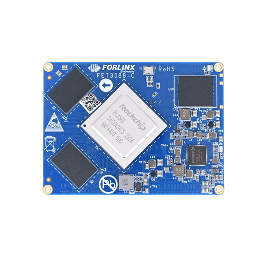
New Release | Forlinx Launches RK3588 SoM And Its Development Board
In November 2022, Forlinx launched FET3588-C SoM and OK3588-C development board, based on Rockchip's new generation flagship RK3588. It’s 4-core [email protected] plus 4-core [email protected]. A great improvement of processing capability and intelligence for AIoT terminals. The SoM can run Android 12.0 now. Ubuntu and Linux will be released later. For further news, please keep following us.
The size of FET3588-C SoM is 50mm x 68mm, an exquisite core board. It carries Rockchip RK3588, 4GB/8GB LPDDR4x, 32GB/64GB eMMC, and adopts board-to-board connection (4*100pin, 0.4 mm spacing, combined height 1.5mm). The module can operate efficiently in working environment of 0℃to 80℃.
OK3588-C development board is to evaluate FET3588-C SoM. Its carrier board has developed a wealth of peripheral devices and interfaces, such as serial ports, 2*USB3.1, 1*PCIe3.0, 2*10/100/1000 Mbps Ethernet, 1*TF card slot, 1*M.2 for 4G/5G Module, 5*MIPI CSI, 2*CAN, WI-FI 6&Bluetooth 5.3, 9*GPIO...with 48 million pixel ISP3.0, support a variety of display interfaces, 1*HDMI 2.1, 1*eDP 1.3, 2*DP 1.4, 2*MIPI-DSI, and four different displays, up to 7680x4320@60Hz, which can provide ultimate visual experience.

OK3588-C Development Board Top-view

OK3588-C Development Board Bottom-view
Forlinx provides RK3588 development kit together with related accessories, optional for OV13850 camera module, 7 '' MIPI display, 4G module, and 5G module to help users develop quickly. Of course, development resources, like kernel and driver source code, user manual, schematic...
Forlinx RK3588 SoM and its development board are available for 4GB DDR4 plus 32GB eMMC and 8GB DDR4 plus 64GB eMMC. For detailed information, please refer to FET3588-C SoM page and OK3588-C development board page.
https://www.forlinx.net/industrial-news/rk3588-som-and-development-board-442.html
1 note
·
View note
Text
What Is The OBD Port and What It Is Used For?

Most of the owners have heard of the OBD port , but where exactly is a OBD port location ? What is this used for?
When we go to car maintenance shop, we will see a mechanic take a dedicated computer tester, accessing to the invisible position of the socket, and then the vehicle's fault code is cleared.
The throttle after cleaning is no longer has an error. In fact, this port is not as mysterious as the imagination, and for the owner, learn to use OBD interface can make you become a car master .
What is the meaning of OBD?
OBD as a proper noun abbreviation, it is all called On Board diagnostics.
This system can do real-time monitoring for engine electronic control system and other functional modules when vehicle running
if found abnormal conditions, it will determine the fault according to specific algorithm, and store the data in the form of diagnostic fault codes (DTC, Diagnostic trouble codes).
After the system has been diagnosed, the useful information will be helpful for the maintenance of the vehicle.
Maintenance staff can read the fault code by using the car's original special instrument . so that the fault can be quickly positioned and reduce the artificial diagnosis time .
Difference between OBD1 and OBD2 ?
Initial OBD system (obd1) has different manufacturers and they were independent and incompatible. in order to unify the standards, the American Association of Automotive Engineers (SAE, Society of Automotive engineers) in 1988 set the OBDII standard.
OBDII implements standard testing procedures and has strict emissions targeting for real-time monitoring of vehicle exhaust emissions.
As a system to monitor exhaust emissions, OBD has gradually expanded its scope of control in the later development. with the increase of various sensors and electronic degree of vehicles, the OBD has incorporated various monitoring functions into its own jurisdiction.
Now we're talking about OBD generally using the word OBD port , because we can only see the transmission interface of the system in the vehicle, but it's combined the whole vehicle control system in back.
The early OBD interface uses the K-line communication method which is based on the ISO protocol. It connects with the external device through the computer standard serial port communication way. But the efficiency is low, so this kind of communication way basically has been eliminated.
In recent years, , CAN-BUS has the very strong expansibility, the popularization of this agreement has made the vehicle detection work greatly simplified, A tester can be used to detect multiple brands of vehicles.
What does a obd2 Scanner do?
OBD2 scanner have below 3 basic function . If you want to know what is the best obd2 scanner ,
please refer to Best OBD2 Scanner Reviews
1.Computer data display
OBD Port as the communication interface of vehicle monitoring system, in addition to reading the fault code to repair the car, the primary function is to provide a variety of vehicle operating conditions.
Except for the vehicle display data, the actual data recorded in the driving computer is much more including a lot of vehicles without a traffic computer display configuration. In fact, the various fuel consumption records, battery voltage, air-fuel ratio, throttle opening, number of explosions and other data are recorded in the system. but some OEM manufacturers remove the traffic computer display due to price allocation and other factors in the lower configuration model vehicle.
It makes users can not refer to these useful data, Therefore, there are some special computer display products on the market.
There are two types of this product, one is connected to the vehicle's OBD interface through a dedicated data line. The data read out and then displayed to the matching display. It is equal to install a traffic computer displays.
Another type of product is the wireless OBD interface adapter + smartphone-side software. This OBD port reader transmits the OBD interface to the smartphone by Bluetooth or WiFi, and presents it to the user through the software on the handset side.
2. Change the code to achieve more functionality
Today's electric control system can access the CAN-BUS of the vehicle control system through the OBD interface. It can adjust the function of each control module of the vehicle.
The most famous application is the data line developed by Ross Tech and the VCDS system diagnostic software.
Most of drivers love to use this equipment to adjust the system of public cars system functions.
3.Read ,Brush and Write ECU TCU program
With the hardware upgrade of the onboard computer system, the program memory of the electronic control unit of the modern vehicle is changed from the previous read-only to the brush able type.
The company is set up to keep the ECU Control procedures to update, like the phone's firmware upgrade . Engine will adapt to a variety of different working environments for different driving areas or conditions through the upgraded ECU system program.
Taking the stability and economy of the original ECU program into consideration , it is generally reserved the power output .
And tuning manufacture can improve the power out by modifying the original ECU data .
Modified program can make the automatic transmission smart and improve the performance of the vehicle .
Everything will be easier when you have the obd port .Just connect your computer to the port by data wire and complete your work .
1 note
·
View note
Text
Unleashing the Power of XBee Modules for Wireless Communication
Wireless communication is an essential technology in today’s world, and it has made our lives easier by allowing us to connect devices without the need for wires. One of the most popular wireless communication technologies is the XBee module, which is used in various applications such as home automation, industrial automation, and remote sensing. In this blog post, we will be discussing the different types of XBee modules and their features.
What is an XBee Module?
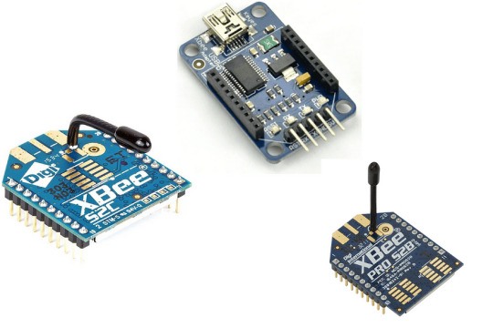
XBee S2C 2mW Wireless Module with Antenna
The XBee S2C 2mW Wireless Module with Antenna is a popular module that provides reliable wireless communication. It has a range of up to 60 meters indoors and up to 1.6 km outdoors, making it suitable for both indoor and outdoor applications. The module uses the ZigBee protocol, which is a low-power wireless communication protocol, and it operates in the 2.4 GHz frequency band.
The module has a built-in antenna, which makes it easy to use and eliminates the need for an external antenna. It also features a low-power sleep mode, which allows the module to conserve power when it is not transmitting or receiving data. The XBee S2C 2mW Wireless Module with Antenna is easy to set up and use, and it is compatible with a wide range of microcontrollers and development boards.
XBEE USB Explorer
The XBEE USB Explorer is a module that provides a simple interface for communication between a PC and an XBee module. It is a USB-based board that allows users to connect an XBee module to their computer and communicate with it using a serial terminal. The module features an FTDI USB-to-serial converter, which provides a virtual COM port for communication with the XBee module.
The XBEE USB Explorer is easy to use and does not require any additional drivers to be installed on the computer. It is compatible with a wide range of XBee modules, including the XBee S2C 2mW Wireless Module with Antenna and the XBee-PRO ZB S2B Extended Range Module. The module is also compatible with a wide range of development boards, including Arduino and Raspberry Pi.
XBee-PRO ZB S2B Extended Range Module
The XBee-PRO ZB S2B Extended Range Module is a high-power module that provides extended-range wireless communication. It has a range of up to 1600 meters outdoors and up to 90 meters indoors, making it suitable for applications that require long-range communication. The module uses the ZigBee protocol and operates in the 2.4 GHz frequency band.
The XBee-PRO ZB S2B Extended Range Module is easy to set up and use, and it is compatible with a wide range of microcontrollers and development boards. It features a low-power sleep mode, which allows the module to conserve power when it is not transmitting or receiving data. The module also has a built-in antenna, which eliminates the need for an external antenna.
Applications of XBee Modules
XBee modules are used in various applications, including home automation, industrial automation, and remote sensing. In home automation, XBee modules are used to connect different devices in the home, such as lighting, security systems, and HVAC systems. They allow these devices to communicate with each other and with a central hub, which enables remote control and monitoring of the devices.
In industrial automation, XBee modules are used to connect different devices in a factory or industrial setting, such as sensors, actuators, and controllers. They allow these devices to communicate with each other and with a central hub, which enables remote monitoring and control of the factory or industrial process.
In remote sensing, XBee modules are used to collect data from sensors and transmit it wirelessly to a central hub for analysis. This is useful in applications such as environmental monitoring, where sensors can be placed in remote locations to collect data on temperature, humidity, and air quality.
XBee modules are also used in the field of robotics, where they enable wireless communication between different components of a robot, such as sensors, motors, and controllers. This allows for greater flexibility in the design and operation of robots, as well as remote control and monitoring of the robot’s activities.
Advantages of XBee Modules
One of the main advantages of XBee modules is their ease of use. They are designed to be easy to set up and use, with a simple interface for communication between devices. This makes them suitable for a wide range of applications, from home automation to industrial automation.
Another advantage of XBee modules is their reliability. They use the ZigBee protocol, which is a low-power wireless communication protocol that is designed to be robust and reliable. This makes XBee modules suitable for applications that require reliable communication, such as industrial automation and remote sensing.
XBee modules also have a low power consumption, which makes them suitable for battery-powered applications. They feature a low-power sleep mode, which allows the module to conserve power when it is not transmitting or receiving data. This makes XBee modules suitable for applications that require long battery life, such as remote sensing and robotics.
Conclusion
In conclusion, XBee modules are a versatile and reliable wireless communication technology that can be used in a wide range of applications, from home automation to industrial automation and remote sensing. They are easy to set up and use, and they offer a simple interface for communication between devices. With their low power consumption and reliability, XBee modules are a great choice for applications that require wireless communication. Whether you are building a home automation system or a remote sensing network, XBee modules are an excellent choice for your wireless communication needs.
0 notes
Text
USB to UART: An Introduction to Serial Communication
USB to UART is a technology that allows serial communication between a computer and a microcontroller or other embedded system. UART, or Universal Asynchronous Receiver-Transmitter, is a standard communication protocol used to transmit and receive data over serial connections. USB to UART adapters are commonly used in embedded systems development, IoT projects, and other applications where serial communication is required.
How Does USB to UART Work?
USB to UART converters consist of a USB connector, a UART interface, and a microcontroller that translates the USB data to UART signals. The USB interface of the adapter connects to the USB port of a computer, while the UART interface connects to the serial port of the embedded system.
The USB to UART adapter typically appears as a virtual COM port on the computer, allowing it to be accessed using standard serial communication APIs. Data transmitted from the computer over the virtual COM port is converted to UART signals and sent to the embedded system. Similarly, data received from the embedded system over the UART interface is converted to USB data and sent to the computer.
Applications of USB to UART
USB to UART adapters are widely used in embedded systems development and IoT projects. Some common applications include:
Programming microcontrollers: USB to UART adapters can be used to program microcontrollers and other embedded systems that use UART for programming.
Debugging: UART is often used for debugging embedded systems, and USB to UART adapters can provide a convenient way to connect to the serial port of the system and view debug output.
IoT projects: Many IoT devices use UART for communication with other devices, and USB to UART adapters can be used to connect these devices to a computer for programming and debugging.
Robotics: Many robotics projects use UART for communication between the robot and a controller, and USB to UART adapters can provide a convenient way to connect the two systems.
Choosing a USB to UART Adapter
When choosing a USB to UART adapter, there are several factors to consider:
Compatibility: The adapter should be compatible with the microcontroller or embedded system you are working with, including the UART interface and voltage levels.
Speed: The speed of the UART interface should match the requirements of your project, including the baud rate and data rate.
Drivers: The adapter should come with drivers that are compatible with your operating system.
Features: Some USB to UART adapters may include additional features, such as programmable I/O pins or voltage level shifting.
Conclusion
USB to UART is a useful technology that provides a convenient way to connect a computer to a microcontroller or other embedded system using serial communication. USB to UART adapters are widely used in embedded systems development, IoT projects, and other applications where serial communication is required. When choosing a USB to UART adapter, it is important to consider factors such as compatibility, speed, drivers, and features to ensure that the adapter meets the requirements of your project.
0 notes
Text
Iview stb3500ii

Iview stb3500ii how to#
Iview stb3500ii serial number#
Iview stb3500ii update#
Iview stb3500ii driver#
Iview stb3500ii upgrade#
Please follow us on Facebook and Twitter for more news, tips, and reviews. Need cord cutting tech support? Join our Cord Cutting Tech Support Facebook Group for help. If you already purchased the Fire TV Recast DVR before the Black Friday sale Amazon is giving $50 credits to customers who already purchased the DVR.ĭid you know we have a YouTube Channel? Every week we have a live Cord Cutting Q&A, and weekly Cord Cutting recap shows exclusively on our YouTube Channel!
Fire TV Recast delivers the most reliable video streams over Wi-Fi of any over-the-air DVR.
Say things like “Alexa, open Channel Guide” or “Alexa, record ‘Riverdale.’” universal remotes will work with an iview-102dv dvd player I can not find the remote code for this dvd player Visit this site by typing the site name Electro.
With a compatible Alexa-enabled device, you can use your voice to search for shows, manage and schedule recordings, and help with other requests.
Plus, store up to 75 hours of HD programming.
With 2 tuners, you can record up to 2 shows at once.
Watch and record live sports, local news, late night shows, and other can’t miss TV from channels available through an HD antenna (sold separately) like ABC, CBS, FOX, NBC, PBS, and The CW.
Fire TV Recast is a DVR that lets you watch and record over-the-air TV at home or on-the-go with a Fire TV, Echo Show, or compatible mobile device-with no monthly fees.
The best part is Amazon just added the ability to add external storage through the USB port. You can get the Fire TV Recast DVR 500GB version for $189.99 or the 1 TB version for $229.99.
The Ultimate Cord Cutting Guide for Sports Fansĭid you miss out on the recent Fire TV Recast sale? Right now Amazon now has The Fire TV Recast DVR again on sale for $50 off.
Here's Everything Coming to Netflix, Hulu, and Prime Video This Week.
Iview stb3500ii how to#
How to Watch Sports on Regional Sports Networks (RSNs).Problems can arise when your hardware device is too old or not supported any longer. This will help if you installed an incorrect or mismatched driver. Try to set a system restore point before installing a device driver.
Iview stb3500ii driver#
It is highly recommended to always use the most recent driver version available. Also make sure you constantly check with our website to ensure that you don't miss a single new release.
Iview stb3500ii update#
Therefore, if you consider applying this release, hit the download button, take into account all the aforementioned aspects, and update the device's firmware. Moreover, it's best that this task be performed in a steady power environment such as the one ensured by a UPS unit.
Iview stb3500ii upgrade#
When it comes to the update steps, due to the large variety of devices and numerous ways for installing a new firmware, it is recommended that you carefully read and understand the upgrade steps, and consider applying a different firmware only when you have familiarized yourself with the update method.Īs the installation process is most of the times quite risky, this step should be taken by users that have the ability to successfully complete the update regular users may initiate it at their own risk. However, bear in mind that applying an older firmware isn't recommended and might not always be possible. On the other hand, downgrading the firmware version can recover the device's functionality in the event of a software update either turning up faulty or causing the unit's overall performance to drop. About Firmware Updates:Īpplying a newer firmware version than the one already installed on your unit can bring various enhancements, include workarounds for diverse problems encountered by the device, and improve or add newly developed features. I contacted Mediasonic technical support and iview technical support and both claimed that they know nothing about this. I now have a Sienoc generic box which does exactly the same thing AND is off date by 5 days (See, it can be worse). Guess what, it did exactly the same thing also.
Iview stb3500ii serial number#
These will Only work for the 3500STBII without CH 3-4 Switch and with 1309 as the first four digits of the Serial Number (SN). I then bought and returned an iView 3500STBII. Select “MENU” again go to “SYSTEM”Select “Restore Factory Default” it needs to reset the box to be able to work. Press “MENU” on the remote Select “SYSTEM”Go to Software Update Select “usb_upgrade_all_flash.bin”Upgrading will show, after finish installing. Copy “flash.bin and usb_upgrade_all_flash.bin” to flash drive. Save and extract the downloadable archive. Instructions for upgrading IV-3500STBII firmware:
1 note
·
View note